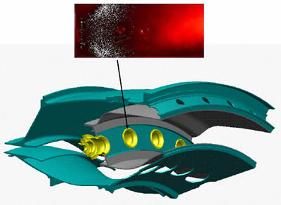
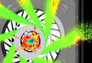
A reduced-scale combustionchamber model is used for the precise reproduction on a test rig of the ignition performances of a complete configuration. A partial model of the Ardiden 1 combustionchamber has been evaluated in altitude conditions on the Mercato test rig (Onera Fauga Mauzac) ... Sector of combustionchamber simulated by the reduced-scale model of the Mercato test rig and viewing of the fuel fog before ignition
ONERA obtains the means to predict the production of emissions in future aeronautical combustionchambers... Faced with this challenge, ONERA has implemented the multi-disciplinary project Cleaner, whose purpose is to allow a very realistic simulation of polluting emissions in future aeronautical combustionchambers
"We have already learned a great deal about the place at which to create the discharge; the choice of the position of the electrodes is very important and is heavily dependent on the combustionchamber and the injector, on their sizes, the rates of combustion, the speed of flow, the pressure, etc."
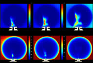
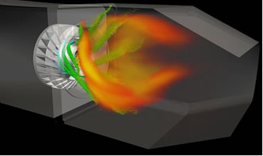
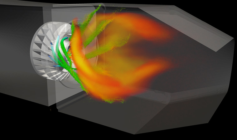
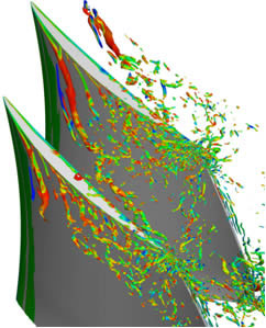
Cedre simulation of two-phase reactive flow in the TLC (Towards Lean Combustion) combustionchamber. Prediction of NOx at less than 10 % and a good prediction of the soot field topology
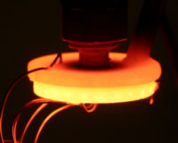
This combustionchamber only measures 20 mm in diameter and is 2 7 mm thick... The flows do not occur in same way at very small scales, for example in the combustionchambers of these micro-turbines, which only measure a few hundred cubic millimetres... This is not desirable for a combustionchamber, where the fuel must mix with air!
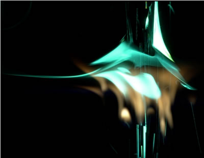
Modeling what happens in the combustionchamber as accurately as possible is very important in the design of more environmentally friendly aircraft engines... Visualization of droplets dispersed in the TLC combustionchamber tested on the M1 test bench at à Onera Palaiseau DEFA computation executed using the CEDRE package
The content of this special issue reflects the diversity of the applications and of the physical conditions where plasmas are applied: from the subsonic to the supersonic regime, from combustionchambers to external aerodynamics, and from thermal plasmas to cold plasmas. Both experimental and modeling aspects are covered, as the complexity of the physics involved render the joint approach necessary
Optimization, especially to reduce consumption, requires the description of the interaction of these vortices with the high pressure gas flow that feeds the combustionchamber. The difficulty in the numerical simulation of this phenomenon is largely due to differences between the characteristic dimensions of the interacting parts: a few tenths of a millimeter for the gap, to a few tens of centimeters for the main flow