
The model hold in the test section can be executed in different manners and depends of the test aim and the available mountings in the wind tunnel.
The mechanical support of the model must respond to several needs:
- to be discrete from the aerodynamic point of view,
- to insure the mechanical hold (with some acceptable mechanical stress and a limited under-load deformation),
- to allow the measurement flow and (eventually) electrical supply,
- to possibly allow the supply and return of the fluids (compressed air, oil...).
When the balance is located inside the model, the mounting must interface with it.
The most common mountings are:
- Single strut support
- Three strut support
- Half model mount
- Straight support
- Z sting support
- Fin sting support
- Twin sting support
- Air inlet mount
- Minimum body mount
ONERA Wind Tunnel Division owns a large choice of mounting elements, generally allowing the cover of usual test needs. The mounting choice is made by our engineers in link with the customer.
However if no support existed for a particular test, we can, case by case and with the help of its Design, Engineering and Fabrication Services, create and manufacture a specific support. The aerodynamic optimisation design of the support can also be realised with the help of the ONERA Applied aerodynamic department (DAAA).
Single strut support
This mounting allows making some alpha and beta range. The balance is external to the model.

A380 test model single strut in F1
|
3 strut support
This mounting allows making some large incidences but no skidding. The balance is external to the model.

Model on 3 strut support in F1
|
Half model mount
The model is directly mounted on the test section floor, on a turret allowing the setting in incidence. A "craft" allows the escape to the limit layer of the vein floor. The 6 balance components is integrated to the turret.
Mounting used at F1, S1MA, S2MA, S3MA.

Half model test in F1
|

Half model test in S1MA
|
Straight support
This kind of support is very classical. It enters in the model at the rear part. It is used for the exploration, the determination of the cruising performances with a capacity of skidding setting.
Mounting used at F1, F2, S1MA, S2MA, S3MA, S4MA.
 Business jet test in S2MA
|
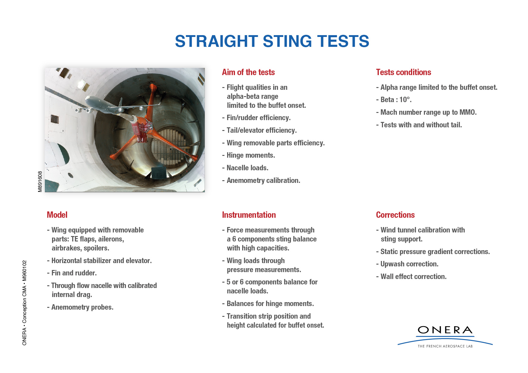 Straight sting support Straight sting support |
Z sting support
This kind of support allows an important clearing of the model rear part. It allows large incidences and is used for the exploration of the flight field. The skidding possibilities are on the other hand very limited.
Mounting used at F1, F2, S1MA, S2MA, S3MA

Commercial aircraft - Z sting in S1MA
|
|

Z sting tests
|
Fin sting support
This kind of support allows a minimisation of the support/model interactions, the mounting blade taking more or less the place of the vertical drift. It is used for the determination of the cruising performances. The skidding possibilities are on the other hand very limited.
Mounting used at F1, F2, S1MA, S2MA, S3MA.

Commercial aircraft on fin sting support in S1MA
|

Twin sting support
The desire to measure the component of total drag attributed to an aircraft's tail assembly, together with the continuing need for better model support corrections, has brought about the design and implementation of twin-sting support for the wind tunnel. This support system was first installed in the S2MA wind tunnel during 1993.
We have since used this slender support successfully for fin-sting, Z-sting, and straight sting interference assessments over the transonic speed range up to Mach 0,82.
The twin-sting support is declared as suitable for commercial tests of models fitted with or without a tail balance, as required by the client.
")
S1MA - Commercial aircraft test on twin sting support (+dummy sting)
|

S2MA - A full span commercial aircraft model on a twin stings
|
Air inlet mount
The mounting for air inlet tests are very specific because they integrate, in addition to the mechanical support function, an air aspiration pipe allowing the simulation of the presence of the aircraft engine.
Mass flow measurement, extractors and control devices are used for air inlet test. With these devices, different points of engine can be simulated.
- A number of venturi (Ø = 50 mm to Ø = 215 mm) and sonic throat (Ø = 1.3 mm to Ø = 135 mm) available.
- A number of obstructors for flow control available.
- 2 flow extractors available (1.8 kg/s and 4.5 kg/s).

Air inlet test in F1
|

Propeller effect on air inlet - S1MA
|
Minimum body mount
Specific mounting for the study of the propellers minimising all the interactions with the support. This type of mounting allows thus the identification of the performances of the propeller itself, before integration on the plane. Generally the motorisation is included in the sting and a 6 component rotating shaft balance allows the determination of the instant strain twister.

Propeller test on minimum body mount in S1MA
|
Helicopter rotor test bench [BERH]
The helicopter rotor test bench [BERH] in operation since 1988 in S1MA. The maximum power available is 550 kW. Two blade rotation directions are feasible. A recent refurbishment of on-board electronic switch compatible with small dimensions of the hub.

Rotor mounted on the BERH setup in S1MA
|
Special mounts
ONERA Wind Tunnel Division can, case by case and with the help of its Design, Engineering and Fabrication Services, creates and manufactures a specific support. The aerodynamic optimisation of the support geometry can also be made with the help of the DAAA department.
 in S1MA")
Cabin test (full size) in S1MA
|

Air Foil Test in S1MA
|