
Large-scale anechoic continuous low-speed wind tunnel, 2m or 3m open-jet test section.
Heated nozzle jet noise testing.

FACILITY DESCRIPTION
CEPRA19 is an open circuit wind tunnel with the following major components :
- A 9 x 9 m inlet featuring a dust filter, acoustic baffles, anti-turbulence screens and a honeycomb,
- A contraction with an inlet diameter of 9 m and two exit diameter: 3 m or 2 m,
- A 9.6 m radius anechoic chamber (quarter of a sphere),
- An acoustically treated flow collector,
- A diffuser,
- A fan silencer with two stages of acoustic baffles,
- A centrifugal fan driven by a 7 MW asynchronous electric motor.
FEATURES
- High quality continuous airflow at Mach number up to 0.38 or 0.18 respectively with 2m or 3m diameter convergent nozzle,
- Very good anechoicity and low background noise in the 200 Hz to 80 kHz frequency bandwidth,
- Nozzle model with bypass duct up to 265 mm, with a continuous total massflow up to 12 kg/s at 500 kPa,
- Nozzle primary jet temperature up to 1150 K supplied by a 2 MW propane burner,
- Nozzle secondary jet temperature up to 450 K (heat from compression alone),
- Nozzle operating conditions are measured with an instrumented rig at the tip of the nozzle rig,
- A 2-axis remotely controlled table is dedicated to adjustement of the airframe positionning relative to the nozzle model during opaerating (controlled with Model Deformation Measurement technique),
- A 3-axis remotely controlled table allows displacement of instrumentation (acoustic antenna, PIV set-up, flow survey device ...).
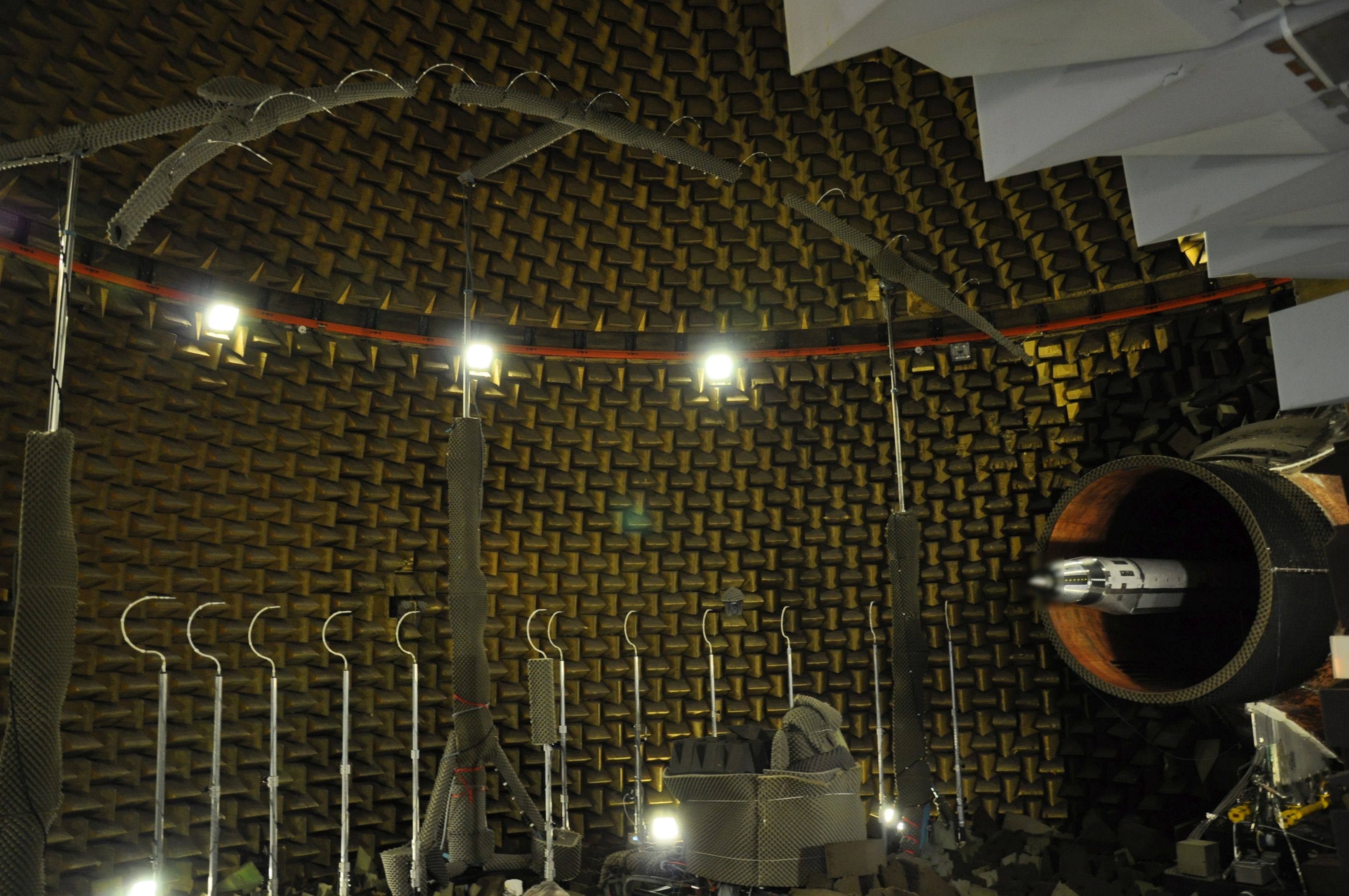
Isolated nozzle test with far field microphones measurement
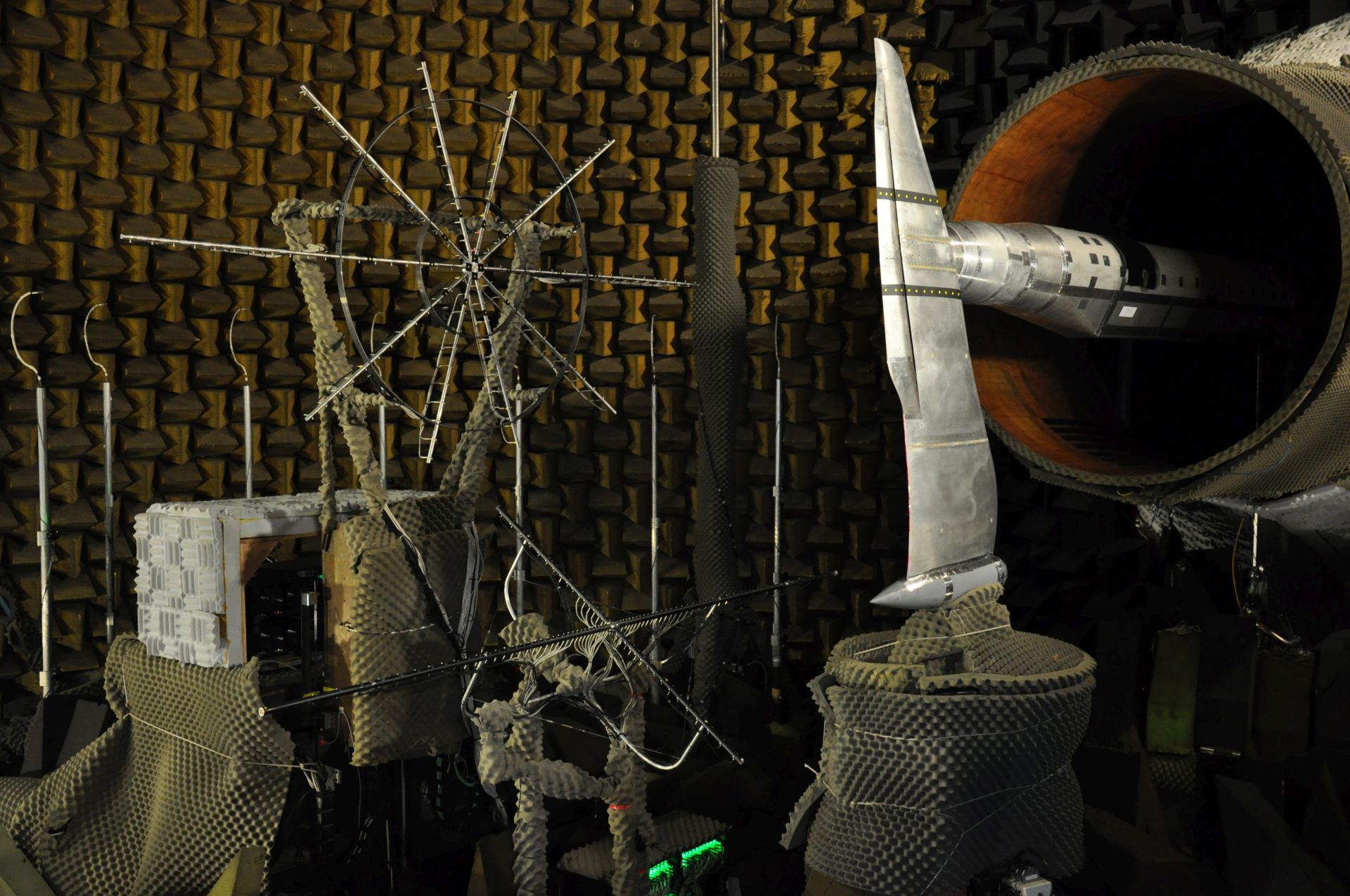
Installed nozzle test with acoustic antenna measurement
TYPICAL TESTS
- Jet noise (hot or cold) with both isolated and installed configurations.
- Airframe noise (High lift Devices noise, landing gear noise ...).
- Noise reduction using micro jet simulator,
- Fan noise using TPS with both isolated and installed configurations,
- Industrial aeroacoustics issues.
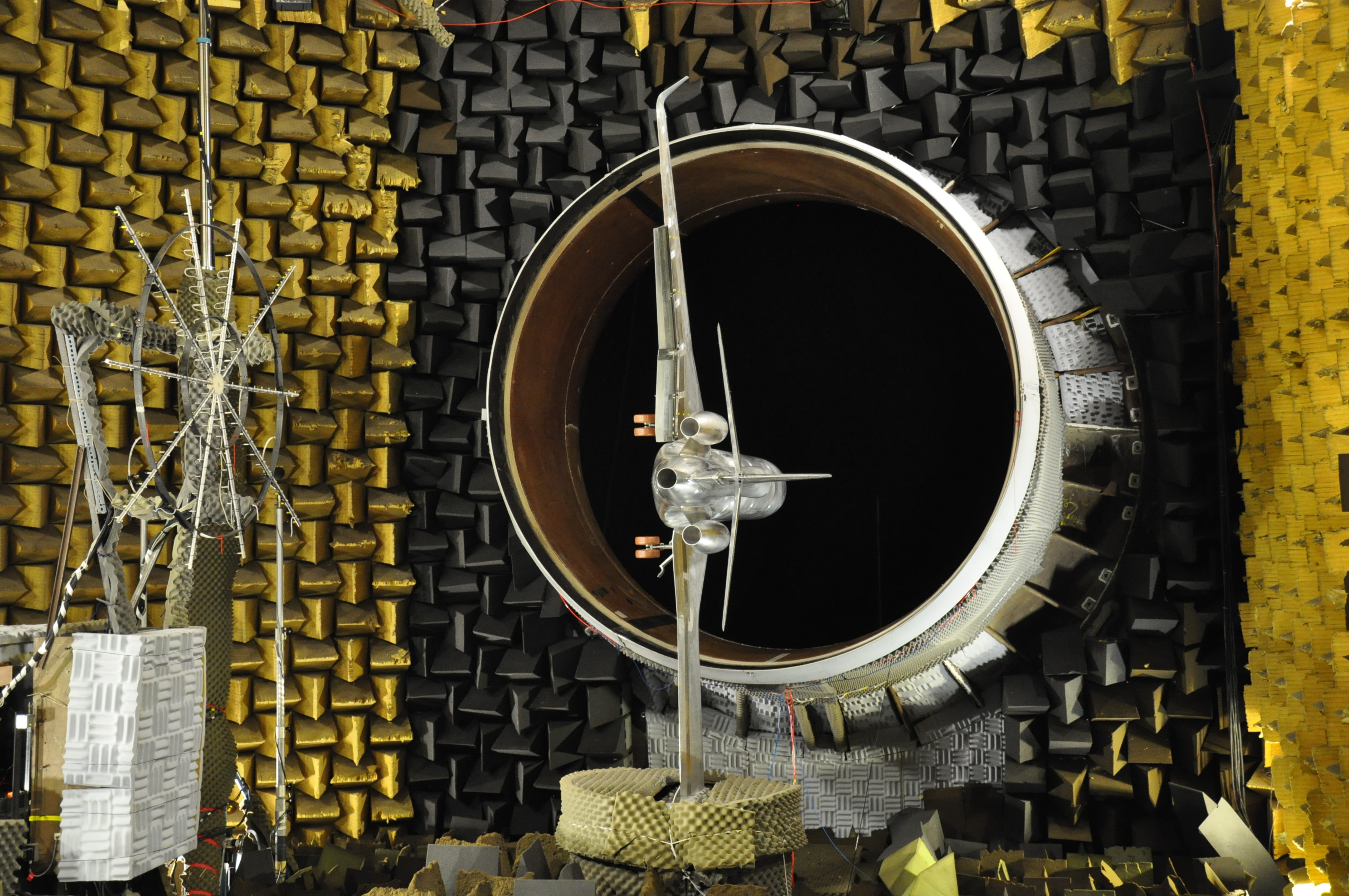
Airframe noise test with acoustic antenna measurement
MEASUREMENT TECHNIQUES
- Far-field microphones measurements with two 6m radius arcs fitted with 12 microphones each, flyover (horizontal plane crossing jet axis) and sideline (longitudinal plane inclined of 56° over the flyover arc plane),
- Acoustic antenna measurements (linear or 2D antenna) for source location,
- Flow survey using probes (five-holes, pressure, temperature),
- 3-component Particle Image Velocimetry (PIV) measurements in longitudinal or transverse planes with air flow and jet flow seeding,
- Visualization by coloured oils.
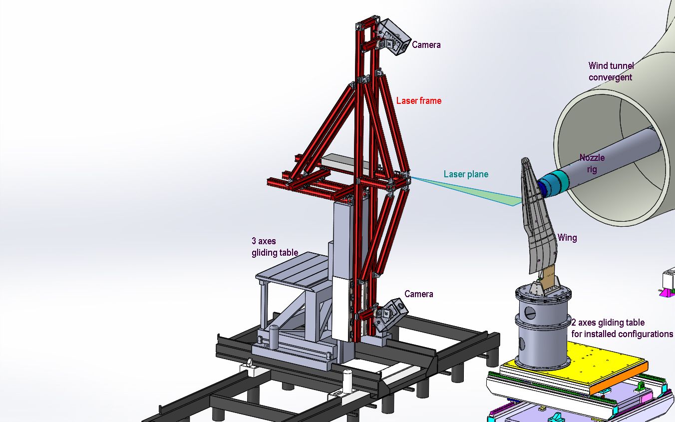
Typical PIV set-up
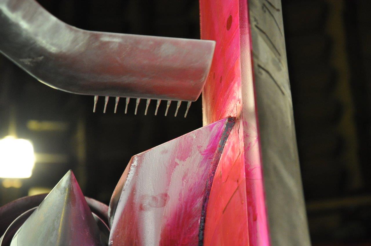
Flow survey and coloured oils visualization
Confidentiality
Secure test preparation and testing sites with card access, data and computer firewalls.