
A campaign for the spectral reflectance measurement of a salt lake in Central Anatolia was conducted in 2010. Many countries were involved.
After the work done in 2009, a campaign of field measurements was conducted to characterize the spectral reflectance of the Tuz Golu salt lake in Central Anatolia. Organized as part of the Committee on Earth Observation Satellites (CEOS) and supported by CNES and the ESA, this campaign gathered laboratories from many countries: Turkey, the United Kingdom, South Africa, Belgium, Brazil, China, South Korea, the United States and Thailand.
The campaign objectives were to compare the field reflectance measurement methods of the various laboratories involved, to characterize the site in terms of temporal and spatial variability, and to provide data for satellite calibration. Several satellites of the participating countries took a total of 40 pictures at the same time as the field measurements. The satellites included: Spot 4 and 5, Landsat5 and 7, Envisat-Meris, Alos-Avnir 1 and 2, EO1-Hyperion, Worldview2, Terra-Modis, UK-DMC 1 and 2, Beijin1, Theos, Rapideye 2, 3 and 4, Kompsat 2, UK-DMC2 and FY3A/VIRR.
An invited session at the IGARSS* congress, to be held in Japan in August 2011, is planned to discuss this field measurement campaign.
* IGARSS: International Geoscience and Remote Sensing System (IEEE)
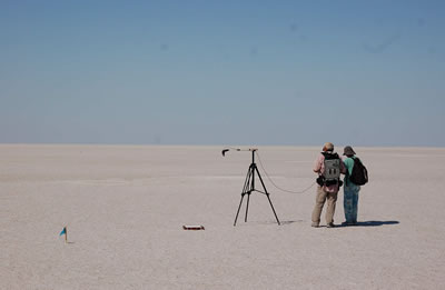
Measurement by Onera of the spectral reflectance of the salt lake over areas with a size that is characteristic of the pixel of satellite imagers.
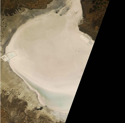
RVB image of the Tuz Golu site on 17/08/2010, taken by the Japanese satellite ALOS-AVNIR2 (© Jaxa) – the two black points in the image correspond to the 50x50m2 trough delimiting the calibration zone