
To render the air movements visible the flow in the wind tunnel has been seeded with very fine submicronic particles, and illuminated by a laser light sheet. These particles follow the stream lines of the vortex, and scatter the laser light reaching the camera.
This image was obtained while developing the Doppler Global Velocimetry technique (DGV). DGV can be used to establish the flow velocity at all points of the zone illuminated by the laser and to draw a map (see below).
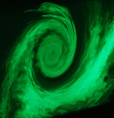
Photograph, taken in a wind tunnel, of the wake vortex of an aircraft at the end of the airfoil. Doppler Global Velocimetry is used to measure the velocity of flow at each point of a plane, illuminated by laser.
Ce cliché a été obtenu dans le cadre du développement d ela technique de vélocimétrie globale à effet Doppler (DGV, pour Doppler Global Velocimetry). La DGV permet d’établir la vitesse de l’écoulement en tous points de la zone éclairée par le laser et d’en dresser la cartographie (voir ci-dessous).
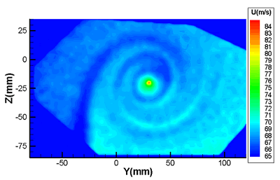
Map of the intensity of the velocity of a wake vortex obtained by DGV. The velocity gets higher toward the centre of the vortex.
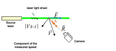
Principle of the measurement
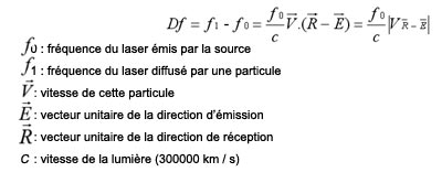
There is a frequency shift Df between the incident wave (fo) onto a particle in movement and the wave that it scatters (f1), as a function of its velocity of displacement. This is what we call the "Doppler effect".
The DGV technique is used to determine this frequency shift Df. We can then obtain a component of the velocity (|VR-E|).
With a computer and optic system based on two CCD cameras and a gas (iodine vapor), the absorption frequencies of which are close to that of the incident beam, we are able to associate the frequency shift Df with a variation of luminous transmission DT.

The first camera directly records the light diffused by the light sheet after the separation of the beam into two. The second one records the other half of the beam after passing through a cell filled with gaseous iodine. We use the absorption properties of iodine to differentiate the emitted and scattered frequencies. The intensities of the second image compared to the first one (called the reference) provide at each point of the image what is needed to draw a transmission map.
One of the absorption lines of iodine, one "edge" of which serves to establish the relation between the frequency shift (f1 - f0) and the corresponding difference in luminous transmission on the image (T1 - T0).
For this method to work, the frequency of the laser source has to be adjusted on an edge, falling or rising of an iodine absorption band.
The Df (f1-f0) are then deduced from the difference between the scattered light and emitted light transmissions.
To measure the 3 components of velocity by this method the same laser sheet has to be observed by 3 optical systems, from different directions, to vary the vector R, or three coplanar laser sheets have to be successively generated (to vary the vector E) and observed by a single optical system.
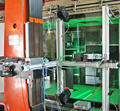
The setup of the DGV system in the F2 wind tunnel of the Onera center at Le Fauga-Mauzac during an Onera/DLR measurement campaign.
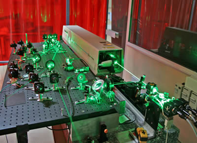
The laser system for DGV in the wind tunnel: several beams are produced, to calibrate the transmission curve for the iodine cell and also to generate three laser light sheets for a three component velocity measurement.
DGV today
Today, this method – DGV – is in competition with another velocimetry method which does not use the coherence properties of laser light: PIV, or Particle Image Velocimetry. PIV, more economical and less complex to implement needs powerful computers. However, for some uses, DGV has decisive advantages: point measurements at high rate, measurement of the velocity of droplets in a spray, three-component at high supersonic, etc.
Moreover DGV is a technique with great educational value and is still popular with students for this reason.
Article written with the help of Christine Lempereur, engineer in the Aerodynamics and Energetics Modeling Department in Toulouse.