
L’image représente le domaine de calcul pour simuler l’écoulement autour d’une maquette d’hélicoptère installée en soufflerie.
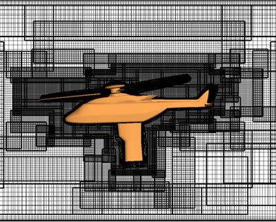
Virtual mock-up of a helicopter in its computational domain. The confusion of the different grids of computation points is a result of the automatic meshing of the space by the CHIMERE method. The corresponding real model is shown at the bottom of the page.
The image represents the computation domain for simulating the flows around a helicopter model set up in a wind tunnel. The space is represented by a large number of sub-domains, or grids, partially overlapping, the “mesh” of which are more or less fine. It is a computational case, called unsteady, as the main rotor and the tail rotor of the helicopter “are rotating” during the numerical simulation.
At first sight this image seems to be incredibly complex. In fact, this is only an apparent complexity. It results from a particular implementation of the Chimère method, a method of numerical computation that is very suitable for the calculation of the interactions of close bodies moving relative to each other. Meshes – or sub-domains, move and overlap at each moment to reflect the changes in geometry with the movements of the bodies. The Chimère method is very suitable for the complete aerodynamic computation of a helicopter where the rotors are rotating, relative to the fuselage.
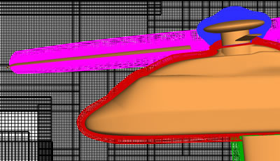
Surface of the helicopter (also called the skin), 3D grids close to the skin (color) and “Cartesian” parallelepiped grids generated automatically
It is only the 3D grids that are input into the simulation software, taking the form of the surface of the helicopter and its components (colored zones in the figure above). The 3D sub-domains in black are parallelepiped grids that are automatically generated and periodically recomputed. These “automatic background grids” always overlap with the totality of the “skin grids” of the helicopter and adapt to the size, fineness, position, all the while taking into account the characteristics of the flow. This technique of automatic mesh generation means particularly that the preparation of the computation can be simplified.
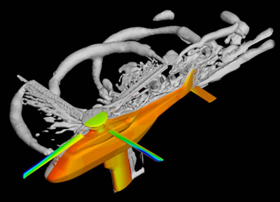
Snapshot of the result of the numeric simulation. The color of the helicopter surface reflects the pressure on the wall of the aircraft. The gray surfaces characterize the wakes of the various parts (iso-surface of the Q criterion).
This study was conducted as part of the European GOAHEAD project. The main objective of this project, which ends in 2010, is to build an experimental wind tunnel database for a complete generic helicopter. Second objective: to validate the different numerical simulation methods of the project's partners, including that of Onera.
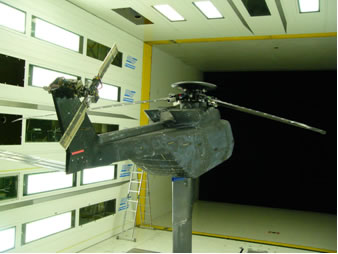
Generic helicopter mock-up for the GOAHED project set up in the LLF wind tunnel (Emmeloord-Pays Bas)
This numerical work has been conducted jointly at Onera by Stéphanie Péron (CFD methods for helicopters [DSNA]), Thomas Renaud and Michel Costes (Applied Helicopter Aerodynamics [DAAP]). Images and quotes recorded by Sylvain Gaultier (Onera web).