- ONERA
- Wind Tunnels
- Testing techniques
- Flow field survey and visualization
Flow field survey and visualization
Several techniques are available in ONERA's wind tunnels :
For flow field survey
- PIV technique
- Flow direction measurement
- Air inlet rake
- Wake survey
- Boundary layer rake
For shockwave arrangement
- Shadowgraph visualization
- Color Schlieren visualization
For surface flow field arrangement
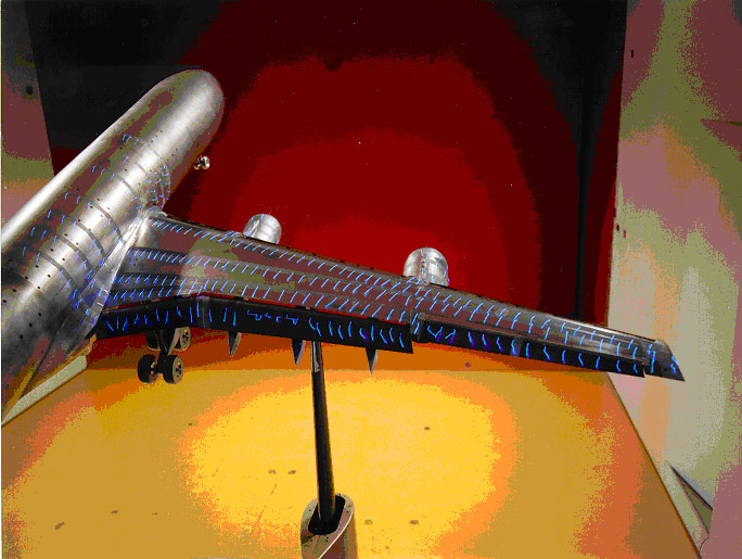
- Mini tuff
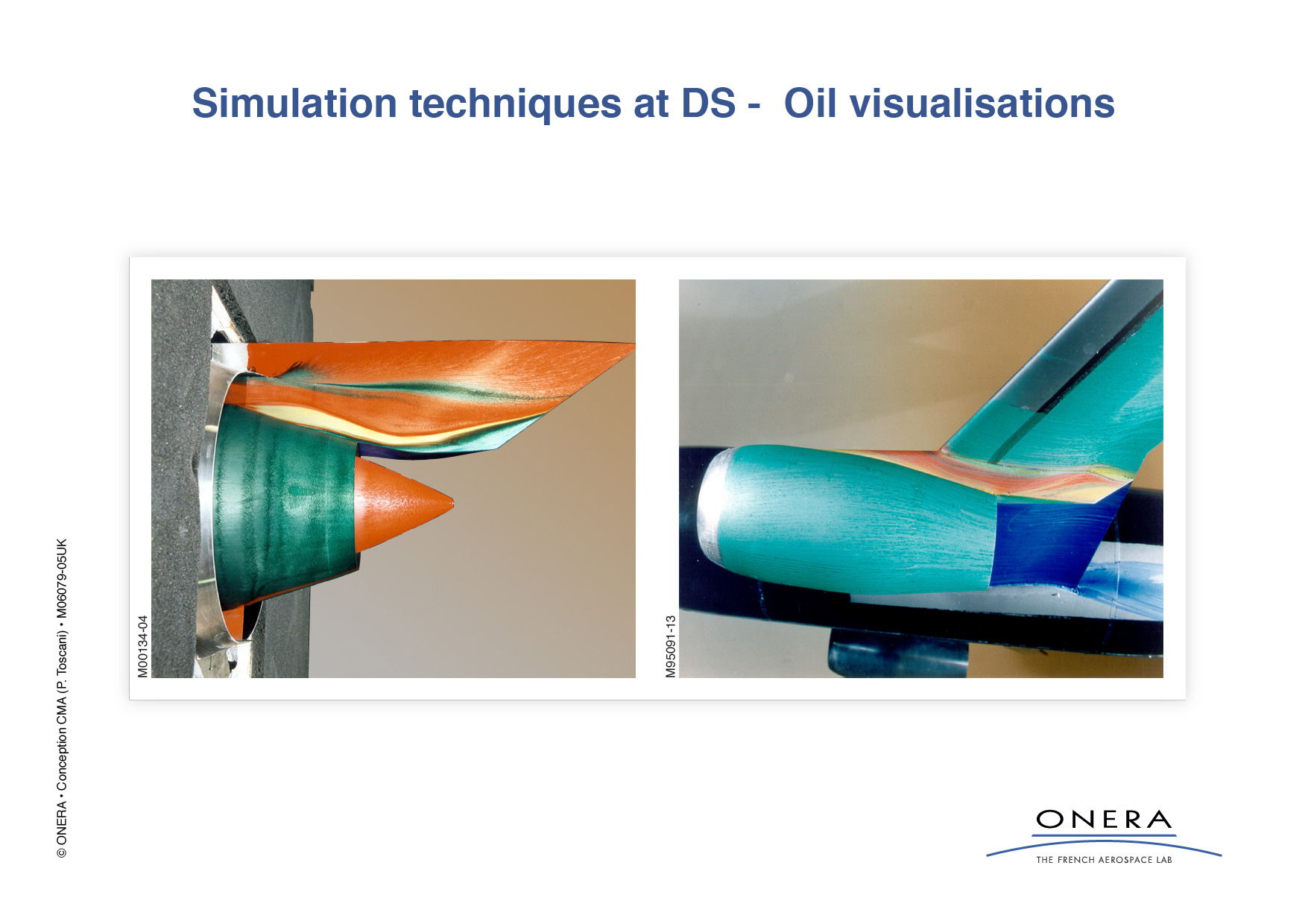
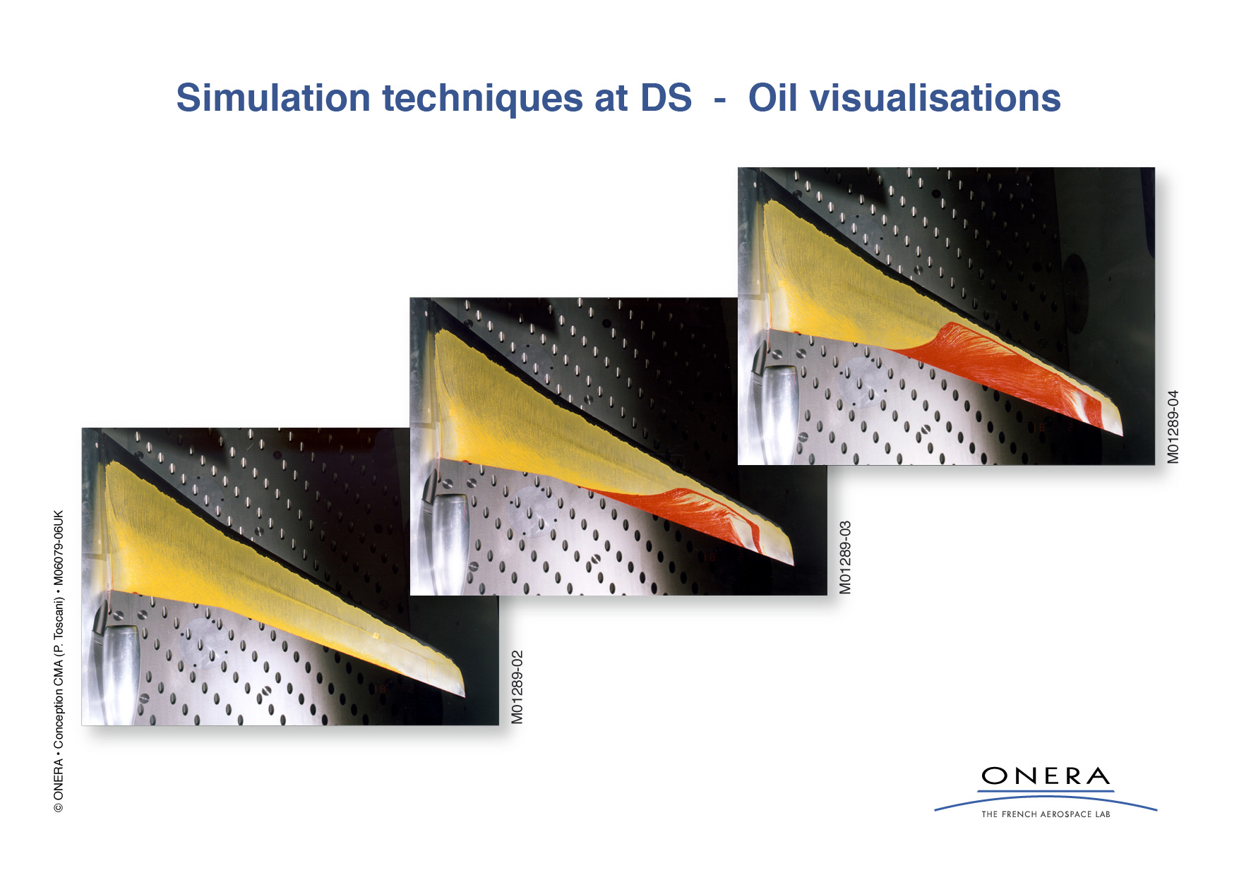
- Colored Oils
PIV
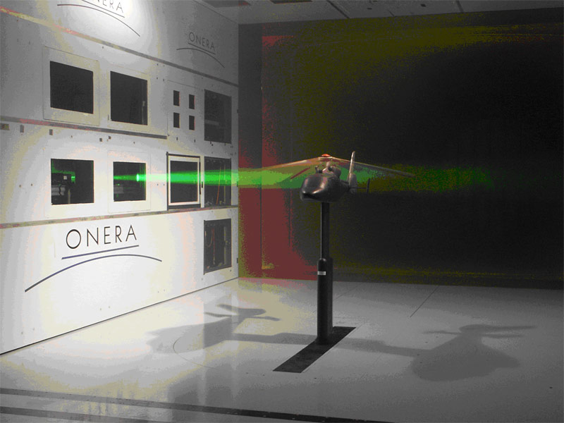
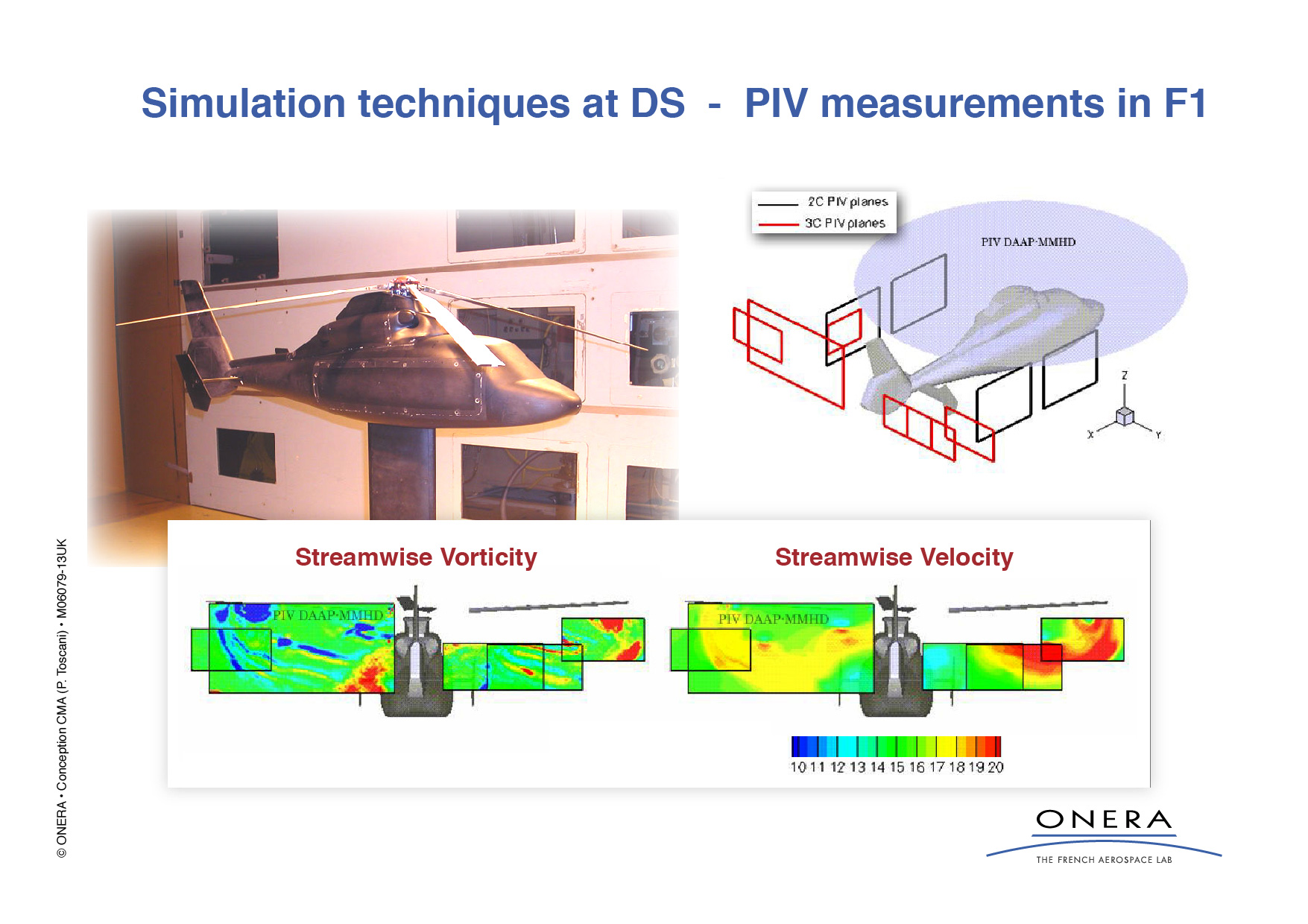
Particle Image Velocimetry (PIV) is a state-of-the-art non-intrusive flow measurement technique. Small tracer particles inside the flow are illuminated twice by very short pulses of a laser light sheet defining the measurement plane. Digital optical sensors capture the light scattered by the particles. Employing image analysis techniques instantaneous velocity vector fields are obtained in high spatial and temporal resolution.
The principle of the PIV measurement technique relies on the physical definition of velocity as a differential quotient. The trajectory of many tracer particles which follow the flow faithfully can be captured with a CCD- or CMOS-camera by illuminating a plane in the flow with two very short light pulses (few nanoseconds) within a time difference of a few microseconds. The two particle images captured at time t and t' are stored on two frames of the CCD- or CMOS- sensor.
This allows to cross-correlate the two particle image distributions in small interrogation areas in order to determine their displacement on many positions of the observation field locally. Using the image magnification factor this method enables the measurement of typically more than 10000 instantaneous velocity vectors for each double-image of the tracer particles inside the light sheet plane. Extending the PIV system to a stereoscopic camera set-up it is possible to determine all three components of the velocity vectors in the plane of the flow field instantaneously.
The main interest of today's research in fluid mechanics is more and more directed to problems where unsteady and separated flows are predominant. For investigations of flow fields with pronounced spatial structures and/or rapid temporal or spatial changes (transition from laminar to turbulent flow, coherent structures, pitching airfoils in transonic flows with shocks, rotors, test facilities with short run time, etc.) new experimental techniques, such as PIV are required which allow to capture the flow velocity of large flow fields instantaneously.
An important feature of PIV is that for the first time, a reliable basis of experimental flow field data is provided for direct comparison with numerical calculations and hence, for validation of computer codes.
For PIV (Particle Image Velocimetry) technique applied in our windtunnels, ONERA Wind Tunnel Division is using the GPU technique and dedicated home-made softwares.
Flow direction measurement - Multi hole pressure probe
Multi hole pressure probes are developed to measure static and total pressure level, and by a preliminary calibration, angle flow (yaw angle and pitch angle) could be determinate. ONERA Wind Tunnel Division design, manufacture and calibrate is own miniature multi hole probes (performed with support from other Onera departments).
- 5 holes
- 3 hole conical probes
- 2 hole two-dimensional probes
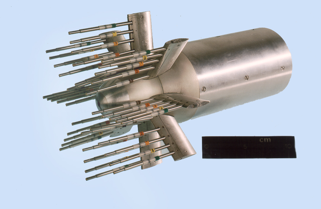
Pressure rake for air inlet study
ONERA has four inlet rakes avalable :
- 2 with an external diamteter of 94mm
- 2 with an external diamteter of 164 mm
- 1 with an external diameter of 185 mm (with 2 motorized arms)
Unsteady and steady rake equipped with 40 Kulite sensors (*) with home made compensation:
1 unit available for high rate acquisition;
- 80 channels,
- Analogue bandwidth 25 kHz,
- Numerical filters and sampling,
- Maximum buffer per channel = 64 k.
(*) Thanks to the thermal compensation, the same Kulite sensor gives the static and the dynamic pressure components.
Wake survey
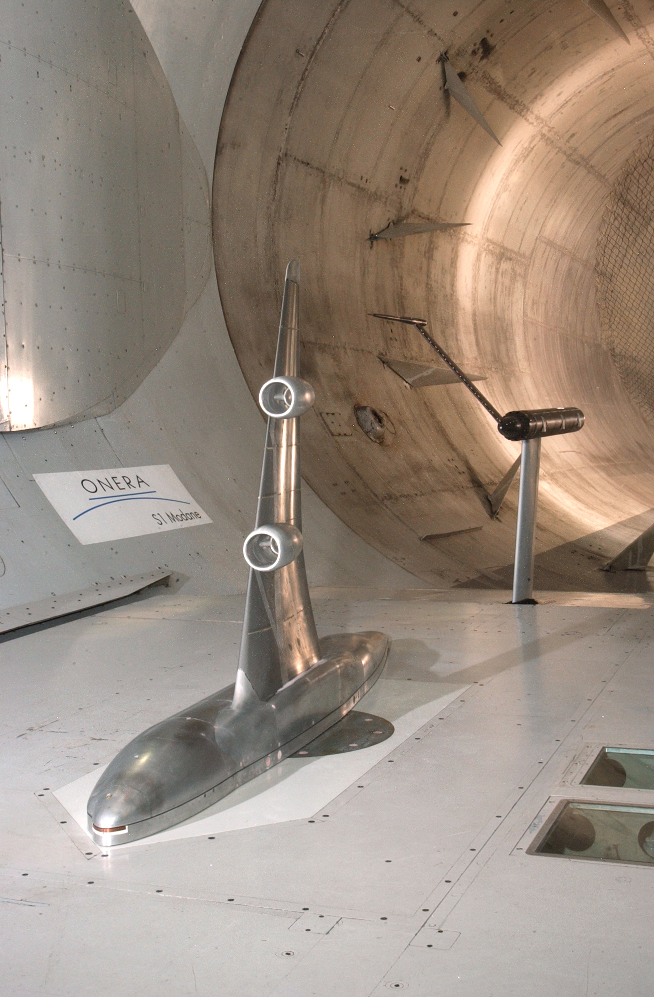
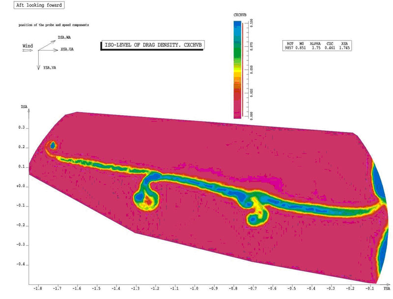
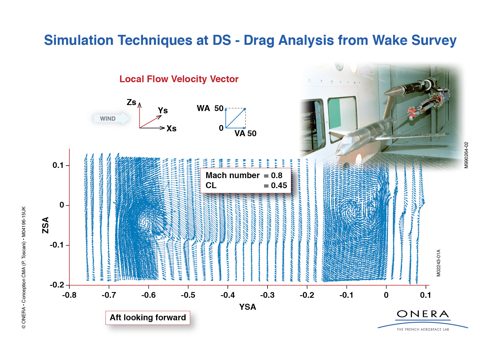
This method is used to determine the different sources of drag associated with an aircraft (viscous drag, shock drag, and induced drag) by velocity and angle measurements performed in its wake.
This device consists of a motorized 5-hole probe mounted (for example with 6-degrees of freedom, usually used for captive trajectory tests or a motorized vertical pole mounted below the test section + a vertical sweptback support mast, which can be moved in the flow + a longitudinal tube equipped with a roll head on its upstream end; a sweeping arm with a sting). The position and attitude of the 5-hole probe in the wind-axis system are determined from various sensors (potentiometer, coding device), taking account of the following deformations in the device (inclinometers ...).
Experiments performed prior to the tests showed that any uncertainties in the probe positioning were of the order of 2mm.
A special calibration of probes, allows the three components of the local velocity vector to be known at each measurement point. The near-field vortex structure, and its evolution between the two measurement planes, can be found, by mapping the projection of the local velocity vectors, and the constant values of the ratio of total probe pressure and tunnel stagnation pressure.
The results are analyzed to identify the various sources of drag (viscous, induced, wave drag, etc.) using the associated tools developed during previous campaigns. Moreover, the results showed good agreement between the global drag (calculated by the wake method), and the measured drag from the model's internal sting balance.
This technique is available in S1MA, F1 and S2MA.
Pressure rake for boundary layer study
Static boundary layer pressure rake: to analyze boundary layer profile. This rake could be design and manufacture on request (static or motorized boundary layer pressure rake).
Shadowgraph visualization
Shadowgraph visualization is an optical method of rendering fluid flow patterns visible y using index of refraction differences in the flow. The method relies on the fact that rays of light bend toward regions of higher refractive index while passing through a transparent material. The fluid is illuminated by a parallel beam of light.
In the wind tunnel, Mach waves and shock waves could be visualized around the model. Images are recorded by means of a CCD camera, digitized and stored in a computer.
This technique is a useful method to understand shock wave arrangements around some complex model.
This technique is available in S2MA and S4A.
Color Schlieren visualization
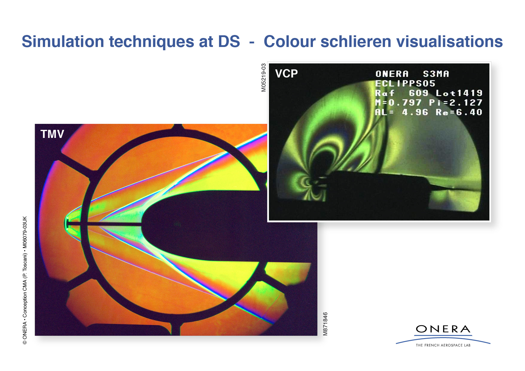
Schlieren flow visualization is based on the deflection of light by a refractive index gradient. The index gradient is directly related to flow density gradient. The deflected light is compared to undeflected light at a viewing screen. The undisturbed light is partially blocked by a knife edge. The light that is deflected toward or away from the knife edge produces a shadow pattern depending upon whether it was previously blocked or unblocked. This shadow pattern is a light-intensity representation of the expansions (low density regions) and compressions (high density regions) which characterize flow.
This technique is available in S3MA.
Surface Flow Field visualization
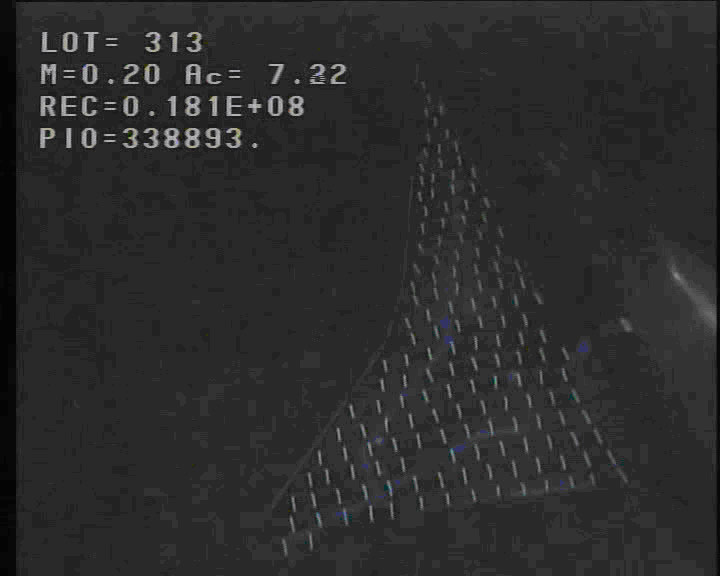
These techniques are very useful to understand aerodynamic phenomena on large surfaces like wings, connection area between fuselage and wing or between nacelle and wing. With cameras, it's possible to observe the flow field evolution during a continuous polar. These techniques are only qualitative and not quantitative techniques. The model has to be prepared before the test and direct optical access is required.
Several techniques are used in ONERA Wind Tunnel Division as follow
Flow Visualization by minitufts with UV Light
Colored oils with natural light
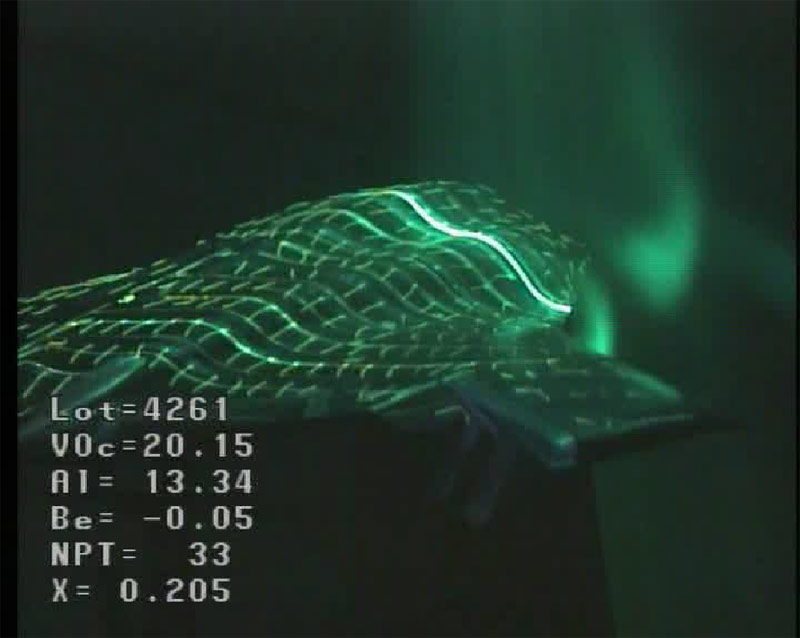
CO2 visualization
Laser velocimetry technique dimensional field in a stream is used in S4B test bench with CO2 seeding.

